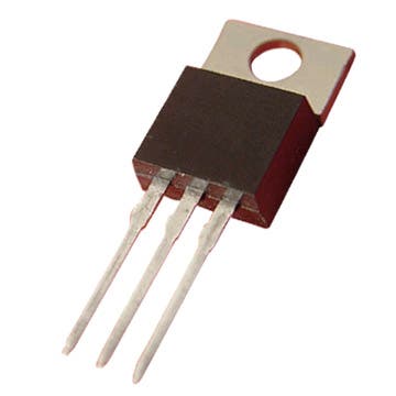
Some transistors :


For Additional Info Click Here..
A small blog to understand the usage of transistor through its simple applications. Created by Ajin.P.A. and Abhi Harshan for Science Fest in St. Joseph's H.S.S. Pavaratty.


Handle ring is connected to +ve of battery. When ring is moving through the wire and it touched on the wire then the red led glow and C1 charges. C maintain this glow for some time. This also keep the T1 turn off. If handle ring reached the end not touching wire the T1 turn on and green LED turn on with C.
 When the reset button presses the capacitor charges fully. Then the positive charge comes to the base of T, through VR ad T1 turns off. This state sustain till the capacitor discharges. This interval is controlled by VR. using this we set the time. To stop the reminder we discharge the capacitor totally. When the capacitor discharge, T turn on and led glows.
 When we connect IC Um 66 to Battery and speaker a small sound is produced.
 Needle is connected to +ve of battery. When needle is moving through the ring and it touched on the ring then the red led glow and C1 charges and the game is over. C maintain this glow for some time. This also keep the T1 turn off. If needle touched on metal surface not touching ring the T1 switch on and green LED turn on with C, then you won the game.

From transmitter the laser light is produced. Place the transmitter and receiver so that the laser beam fall on LDR. When laser falls on LDR this turns off t1. When the beam split by a tress passer or burglar LDR stops conducting and t1 turns on and LED glows. C store Voltage and Maintains this glow.

 The transistors BC 548(T2), BC 188(T1), and capacitor 0.01(C1) muF makes an oscillation circuit and makes a continues vibration on the speaker coil. The frequency of the vibration is depended on the resistance given to the base of T2. This vibration becomes a sound of corresponding frequency. Through the switches the resistance is given in particular value and this creates different sounds.
 When electricity is available transformer will provide 6v output. This passes through diode and charges battery. But the (+)ve charge from transformer turn off PNP transistor and light don’t glow.